Linear drives: 8 advantages of rack and pinion
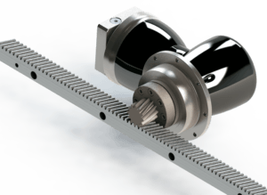 How do you make a low-backlash movement in the horizontal or vertical direction, in other words: from rotating to linear?
The real expert knows that without a doubt, but only the specialist in mechanical drive technology knows all possibilities with the associated advantages and disadvantages.
In this article we give a number of possibilities to make a correct choice for a linear drive.
Most used linear drives
Roughly the following (most used) possibilities are known to realize linear drives:
- Spindle
- Timing belt
- Rack and pinion
- Linear motor
- Push chain
Below a small explanation of each drive with the advantages and disadvantages.
 Spindle linear drive
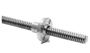
A spindle is a kind of threaded shaft, over which a nut can move back and forth when the shaft is rotated and thus a linear movement can be created. The nut is often equipped with (small) balls for less friction and higher loads. That is why the combination is called a ball-screw spindle. If ball-screws are not used, the thread is often “angled” and the thread is named “trapezium”.
A spindle is a fast, mechanical way for a limited linear adjustment. The biggest disadvantage is that the length is limited and the speed cannot be high due to swinging. A typical spindle drive is for example a scissor jack of a car. A spindle is also often the heart of an “actuator”.
 Linear drive with timing belt
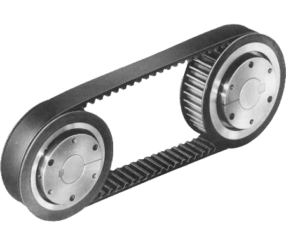
A timing belt is stretched over pulleys and is toothed to prevent slippage. A timing belt is often the heart of a so-called linear module, where the ends of the toothed belt come together in the moving part. An advantage of this drive is that it is cheap and easy to build, the disadvantage is the required pre-tension and occurring inaccuracy in connection with the (mostly limited) elongation of the timing belt. A timing belt drive can also be used to distribute a rotation, with or without different ratio’s.
The timing belt is driven by a shaft with pulley and this allows the torque to increase significantly. For this reason, a gearbox is mounted for these drives to reduce the speed and to increase the torque. Especially for timing belt drives, Apex Dynamics has introduced the PL (straight) and PLR (right-angled), with heavier bearings and a very compact design. A typical linear timing belt drive is the print-head of a printer or an electric garage door, a typical rotary timing belt drive and a timing belt of a combustion engine.
 Rack and pinion linear drive
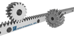
A rack has the property that it can be infinitely long and the accuracy, when assembled correctly, does not decrease. The pinion runs back and forth over the rack (in fact a gear with an infinite radius). Racks can be mounted together and are normally available in lengths from 500 mm up to 2000 mm. Several pinions can run over a toothed rack in order to carry out different movements simultaneously or to execute the movement simultaneously with double force. The pinion is often mounted on a gearbox, which increases the torque and reduces the speed. A typical rack application is a gate drive or a bridge drive.
If 2 motors with pinions are installed as a master slave, the drive is backlash free.
 Linear motor
A linear motor is a drive that, like an electric motor, is based on an alternating magnetic field. In essence, it is an electric motor with a “rolled out” stator. Instead of a rotating movement, this type of motor produces a linear movement, and can in principle be as long as necessary. A Linear motor consists of a (theoretically) infinitely long row of electromagnets. The object to be driven contains a fin of a conductive material, usually aluminium or copper. The electromagnets create a continuous linear “wave” in which vortex currents are produced in the fin, causing an opposite field. This is how the fin begins to move, with some slip, in the wave of magnetism.
A typical example of a linear motor is, for example, a magnetic levitation train. Due to the very high costs of material and technology and the low torque, this kind of drive is not used often.
 Linear drive by Push chain
The push chain consists of specially shaped links, which due to the geometry ensure that the chain cannot buckle under pressure. It is driven by a kind of geared wheel over which the push chain can roll. It should be taken into account that the end of the push chain cannot be used, this is why often a construction to roll it up is required. The first execution of a push chain was described by Leonardo da Vinci, but only applied industrially since WWII.
A well-known example of a push chain is the Continuously Variable Transmission from Bosch / van Doorne.
Overview of the different linear drives
The table below shows the strengths and weaknesses of each drive: (“-” = worse, “0” = neutral and “+” is better)
| Spindle | Timing belt | Rack and Pinion | Linear motor | Push chain | |
| Speed | + | + | ++ | ++ | + |
| Force | + | + | ++ | – | ++ |
| Acceleration | 0 | + | + | + | 0 |
| Accuracy | ++ | 0 | ++ | + | 0 |
| Stroke length | – | – | ++ | ++ | – |
| Suitable for vertical | ++ | 0 | ++ | – | ++ |
| Life time | 0 | + | + | ++ | 0 |
| Investment costs | + | ++ | 0 | — | 0 |
| Efficiency | + | – | + | – | 0 |
| Repair costs | – | 0 | + | – | – |
| Easy assembly | + | ++ | + | – | + |
What is the best linear drive for your application?
This depends on many factors, above you will find the most important. Are you working on a linear drive and can you use a sparring partner? Please contact Apex Dynamics.
 Linear drive with timing belt
 Rack and pinion linear drive
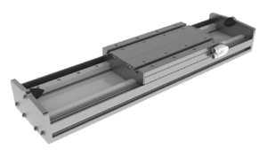 Linear motor
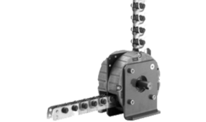 Linear drive by Push chain


