ATB-FC series
- Steel black oxidized housing
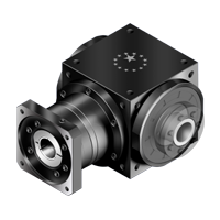
- Spiral bevel gearbox with a continuous hollow shaft and motor flange on the input side
- Ratio 1 to 500
- Spiral bevel gearbox with output hollow shaft thru without keyway. Both ends with shrink disc power lock. Input with motor adapter.
- Steel housing, black oxidized, aluminum black anodized motor adapter plate
- Steel hollow output shaft with two shrinks discs (are included)
- Spiral bevel gears, planetary part with spur gears
- Nominal torques:
- T2N : 12 Nm - 3.200 Nm
- Ratios
- 1-stage : 1 / 1,5 / 2 / 3 / 4 / 5
- 2-stage : 7 / 10 / 15 / 20 / 25 / 35 / 50
- 3-stage : 75 / 100 / 125 / 150 / 200 / 250 / 350 / 500
- Low backlash
- 1-stage : ≤ 6 arcmin
- 2-stage : ≤ 8 arcmin
- 3-stage : ≤ 10 arcmin
- high efficiency
- 1-stage: ≥ 98%
- 2-stage : ≥ 94%
- 3-stage : ≥ 94%
- Easy mount
- Low Noise
- Compact structure
- Sizes available: ATB065FC / ATB075FC / ATB090FC / ATB110FC / ATB140FC / ATB170FC / ATB210FC / ATB240FC / ATB280FC
|
Model No. |
Stage | Ratio1 | ATB065 FC |
ATB075 FC |
ATB090 FC |
ATB110 FC |
ATB140 FC |
ATB170 FC |
ATB210 FC |
ATB240 FC |
ATB280 FC |
|
| Nominal Output Torque T2N | Nm | 1 | 1 | 25 | 45 | 78 | 150 | 360 | 585 | 1,300 | 2,150 | 3,200 |
| 1.5 | 25 | 45 | 78 | 150 | 360 | 585 | 1,300 | 2,150 | 3,200 | |||
| 2 | 24 | 42 | 68 | 150 | 330 | 544 | 1,220 | 2,010 | 3,050 | |||
| 3 | 18 | 33 | 54 | 120 | 270 | 450 | 1,020 | 1,650 | 2,850 | |||
| 4 | 13 | 28 | 48 | 100 | 224 | 376 | 860 | 1,410 | 2,300 | |||
| 5 | 12 | 25 | 40 | 85 | 196 | 320 | 740 | 1,210 | 2,000 | |||
| 2 | 7 | 12 | 12 | 33 | 91 | 91 | 91 | 195 | 358 | 358 | ||
| 10 | 24 | 28 | 68 | 150 | 208 | 208 | 430 | 846 | 846 | |||
| 15 | 18 | 33 | 54 | 120 | 270 | 312 | 645 | 1,269 | 1,269 | |||
| 20 | 13 | 28 | 48 | 100 | 224 | 376 | 860 | 1,410 | 1,629 | |||
| 25 | 12 | 25 | 40 | 85 | 196 | 320 | 740 | 1,210 | 2,000 | |||
| 35 | 12 | 25 | 40 | 85 | 196 | 320 | 740 | 1,210 | 1,790 | |||
| 50 | 12 | 25 | 40 | 85 | 196 | 320 | 740 | 1,210 | 1,465 | |||
| 3 | 75 | - | - | - | 120 | 210 | 312 | 585 | 1,269 | 1,269 | ||
| 100 | - | - | - | 100 | 224 | 376 | 780 | 1,410 | 1,692 | |||
| 125 | - | - | - | 85 | 196 | 320 | 740 | 1,210 | 2,000 | |||
| 150 | - | - | - | 120 | 135 | 312 | 390 | 975 | 975 | |||
| 200 | - | - | - | 100 | 180 | 376 | 520 | 1,300 | 1,300 | |||
| 250 | - | - | - | 85 | 196 | 320 | 650 | 1,210 | 1,625 | |||
| 350 | - | - | - | 85 | 196 | 320 | 740 | 1,210 | 1,790 | |||
| 500 | - | - | - | 85 | 196 | 320 | 740 | 1,210 | 1,465 | |||
| Max. Acceleration Torque T2B | Nm | 1,2,3 | 1~500 | 1.5 times Nominal Output Torque T2N | ||||||||
| Max. Acceleration Input Speed n1B | rpm | 1 | 1~5 | 7,500 | 6,500 | 5,500 | 4,500 | 3,500 | 3,000 | 2,200 | 2,000 | 1,700 |
| 2 | 7~50 | 8,000 | 8,000 | 6,000 | 6,000 | 6,000 | 6,000 | 4,800 | 3,600 | 3,600 | ||
| 3 | 75~500 | - | - | - | 8,000 | 8,000 | 6,000 | 6,000 | 6,000 | 6,000 | ||
| Backlash(2) | arcmin | 1 | 1~5 | ≤ 6 | ≤ 6 | ≤ 6 | ≤ 6 | ≤ 6 | ≤ 6 | ≤ 6 | ≤ 6 | ≤ 6 |
| 2 | 7~50 | ≤ 8 | ≤ 8 | ≤ 8 | ≤ 8 | ≤ 8 | ≤ 8 | ≤ 8 | ≤ 8 | ≤ 8 | ||
| 3 | 75~500 | - | - | - | ≤ 10 | ≤ 10 | ≤ 10 | ≤ 10 | ≤ 10 | ≤ 10 | ||
| Max. Radial Load F2rB2 (3) Output d2 |
N | 1,2,3 | 1~500 | 900 | 1,100 | 1,700 | 2,700 | 4,800 | 6,600 | 11,500 | 16,000 | 18,000 |
| Max. Axial Load F2aB2 (3) Output d2 |
N | 1,2,3 | 1~500 | 450 | 550 | 850 | 1,350 | 2,400 | 3,300 | 5,750 | 8,500 | 9,000 |
| Efficiency | % | 1 | 1~5 | ≥ 98 % | ||||||||
| 2,3 | 7~500 | ≥ 94 % | ||||||||||
| Weight | kg | 1 | 1~5 | 2.9 | 4.4 | 7.2 | 11.8 | 20.4 | 35.0 | 66.5 | 96.0 | 151.7 |
| 2 | 7~50 | 3.3 | 4.9 | 8.2 | 14.1 | 24.1 | 37.4 | 71.2 | 107.2 | 164.4 | ||
| 3 | 75~500 | - | - | - | 13.7 | 23.5 | 37.5 | 70.5 | 105.0 | 162.2 | ||
| Operating Temp | ºC | 1,2,3 | 1~500 | -10ºC~+90ºC | ||||||||
| Lubrication | 1,2,3 | 1~500 | Synthetic Iubrication | |||||||||
| Noise Level(4) | dB(A) | 1,2,3 | 1~500 | ≤71 | ≤72 | ≤76 | ≤77 | ≤78 | ≤79 | ≤81 | ≤83 | ≤84 |
- Ratio ( i = N in / N out )
- Backlash is measured at 2% of Nominal output torque T2N
- Applied to the input shaft center at n1B
- These values are measured by gearbox with ratio 5 (1-stage), ratio 50 (2-stage) or ratio 500 (3-stage) at 1,500 rpm no loading.
By lower ratio and/or higher RPM, the noise level could be 3 to 5 dB higher.
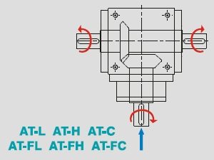
Rotation Direction
Maximum radial and axial loads:
The maximum radial and axial loads on the output shaft of the gearbox depends on the design of the gearbox supporting bearings.
Apex Dynamics uses the extension straddle oversized ball bearing design. This can take heavy load from both axles
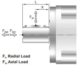
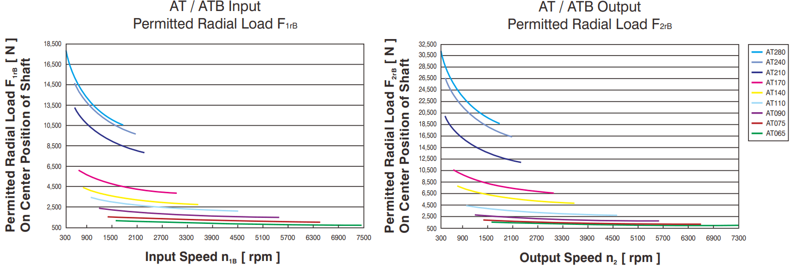
Permitted radial load F2r on center of output shaft X = ½ x L for various output speeds.
If radial force F2r is not exerted on the center of the ouput shaft X < ½ x L or X > ½ x L, the permitted radial and axial loads can be calculated by the position load factor Kb on the above diagram.
|
Model No. |
Stage | Ratio1 | ATB 065FC |
ATB 075FC |
ATB 090FC |
ATB 110FC |
ATB 140FC |
ATB 170FC |
ATB 210FC |
ATB 240FC |
ATB 280FC |
|
| Massa Moment of inertia J1 |
kg*cm2 | 1 | 1 | 0.51 | 1.30 | 3.14 | 7.62 | 23.54 | 59.09 | 195.96 | 365.38 | 787.63 |
| 1.5 | 0.46 | 1.15 | 2.80 | 6.65 | 19.34 | 49.38 | 156.02 | 279.62 | 584.28 | |||
| 2 | 0.44 | 1.10 | 2.68 | 6.23 | 17.72 | 45.44 | 140.80 | 245.78 | 500.26 | |||
| 3 | 0.43 | 1.09 | 2.64 | 6.08 | 17.16 | 44.11 | 135.51 | 233.75 | 471.56 | |||
| 4 | 0.43 | 1.08 | 2.63 | 6.05 | 17.03 | 43.79 | 134.14 | 230.77 | 464.76 | |||
| 5 | 0.43 | 1.08 | 2.63 | 6.04 | 16.99 | 43.69 | 133.71 | 229.71 | 462.08 | |||
| 2 | 7 | 0.15 | 0.15 | 0.50 | 2.79 | 2.79 | 2.79 | 9.91 | 29.26 | 29.26 | ||
| 10 | 0.15 | 0.15 | 0.50 | 2.80 | 2.80 | 2.80 | 9.96 | 29.43 | 29.43 | |||
| 15 | 0.15 | 0.15 | 0.50 | 2.80 | 2.80 | 2.80 | 9.96 | 29.43 | 29.43 | |||
| 20 | 0.15 | 0.15 | 0.50 | 2.80 | 2.80 | 2.80 | 9.96 | 29.43 | 29.43 | |||
| 25 | 0.15 | 0.15 | 0.50 | 2.80 | 2.80 | 2.80 | 9.96 | 29.43 | 29.43 | |||
| 35 | 0.15 | 0.15 | 0.50 | 2.79 | 2.79 | 2.79 | 9.91 | 29.26 | 29.26 | |||
| 50 | 0.15 | 0.15 | 0.50 | 2.79 | 2.79 | 2.79 | 9.89 | 29.20 | 29.20 | |||
| 3 | 75 | - | - | - | 0.15 | 0.15 | 0.50 | 0.50 | 2.80 | 2.80 | ||
| 100 | - | - | - | 0.15 | 0.15 | 0.50 | 0.50 | 2.80 | 2.80 | |||
| 125 | - | - | - | 0.15 | 0.15 | 0.50 | 0.50 | 2.80 | 2.80 | |||
| 150 | - | - | - | 0.15 | 0.15 | 0.50 | 0.50 | 2.79 | 2.79 | |||
| 200 | - | - | - | 0.15 | 0.15 | 0.50 | 0.50 | 2.79 | 2.79 | |||
| 250 | - | - | - | 0.15 | 0.15 | 0.50 | 0.50 | 2.79 | 2.79 | |||
| 350 | - | - | - | 0.15 | 0.15 | 0.50 | 0.50 | 2.79 | 2.79 | |||
| 500 | - | - | - | 0.15 | 0.15 | 0.50 | 0.50 | 2.79 | 2.79 | |||
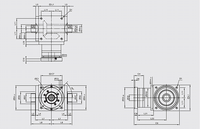
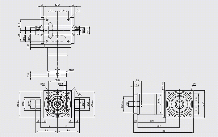
ATB-FC series 1-stage, ratio i = 1 ~ 5
| ATB065FC | ATB075FC | ATB090FC | ATB110FC | ATB140FC | ATB170FC | ATB210FC | ATB240FC | ATB280FC | |
| D1 | M4 | M6 | M6 | M8 | M10 | M12 | M16 | M16 | M16 |
| D2 H6 | 13 | 14 | 18 | 22 | 32 | 40 | 50 | 55 | 60 |
| D3 h8 | 16 | 16 | 22 | 25 | 44 | 50 | 62 | 68 | 75 |
| D4 h7 | 63 | 73 | 88 | 108 | 135 | 165 | 205 | 235 | 275 |
| D12 | 62 | 72 | 86 | 106 | 104 | 128 | 160 | 180 | 200 |
| D14 h7 | 63 | 73 | 88 | 108 | 135 | 165 | 205 | 235 | 275 |
| D15 | 62.9 | 72.9 | 87 | 107 | 105 | 130 | 158 | 178 | 198 |
| D17 | 26 | 26 | 36 | 38 | 61 | 70 | 86 | 86 | 100 |
| D18 | 41 | 41 | 50 | 50 | 80 | 90 | 110 | 115 | 138 |
| L1 | 65 | 75 | 90 | 110 | 140 | 170 | 210 | 240 | 280 |
| L2 | 14 | 14 | 18 | 18 | 24 | 26 | 29 | 29 | 30.5 |
| L3 | 13 | 14.5 | 15 | 15 | 15 | 15 | 20 | 25 | 25 |
| L4 | 2 | 2 | 2 | 2 | 2 | 2 | 2 | 2 | 2 |
| L7 | 47.5 | 54 | 62 | 72 | 87 | 102 | 127 | 147 | 167 |
| L8 | 66 | 72.5 | 85 | 95 | 116.5 | 133.5 | 161.5 | 181.5 | 205 |
| L11 | 27 | 30 | 36 | 44 | 55 | 67 | 85 | 95 | 110 |
| L13 | 13 | 15 | 15 | 15 | 15 | 15 | 20 | 25 | 25 |
| L21 | 49 | 60.5 | 63 | 69.5 | 85.5 | 95 | 130 | 144.5 | 135 |
| L22 | 81.5 | 98 | 108 | 124.5 | 155.5 | 180 | 235 | 264.5 | 275 |
| L23 | 15 | 15 | 20 | 20 | 26 | 28 | 31 | 31 | 32.5 |
| L24 | 15 | 15 | 20 | 20 | 26 | 28 | 31 | 31 | 32.5 |
| L25 | 15 | 15 | 19.5 | 19.5 | 25.5 | 27.5 | 30.5 | 30.5 | 32.5 |
| L26 | 18.5 | 18.5 | 23 | 23 | 29.5 | 31.5 | 34.5 | 34.5 | 38 |
| C1 1 | 46 | 70 | 100 | 100 | 130 | 165 | 215 | 215 | 235 |
| C2 1 | M4 | M5 | M6 | M6 | M8 | M10 | M12 | M12 | M12 |
| C3 1 | ≤11 / ≤122 | ≤14 / ≤15.875 / ≤162 | ≤19 | ≤24 | ≤32 | ≤38 | ≤42 | ≤48 | ≤55 |
| C4 1 | 30 | 34 | 40 | 40 | 50 | 60 | 85 | 85 | 116 |
| C5 1G6 | 30 | 50 | 80 | 80 | 110 | 130 | 180 | 180 | 200 |
| C6 1 | 3.5 | 8 | 4 | 4 | 5 | 6 | 6 | 6 | 6 |
| C7 1 | 42 | 60 | 90 | 90 | 115 | 142 | 190 | 190 | 220 |
| C8 1 | 19.5 | 19 | 17 | 17 | 19.5 | 22.5 | 29 | 29 | 63 |
| C9 1 | 133.5 | 154.5 | 170 | 196.5 | 245 | 287.5 | 369 | 413.5 | 478 |
| C10 1 | 13.25 | 13.5 | 10.75 | 10.75 | 13 | 15 | 20.75 | 20.75 | 53.5 |
1. C1~C10 are motor specific dimensions (metric std shown).
2. ATB065 FCM1 offers C3 ≤ 12 option, ATB075 FCM1 offers C3 ≤ 16, ATB075 FCM2 offers ≤ 15.875
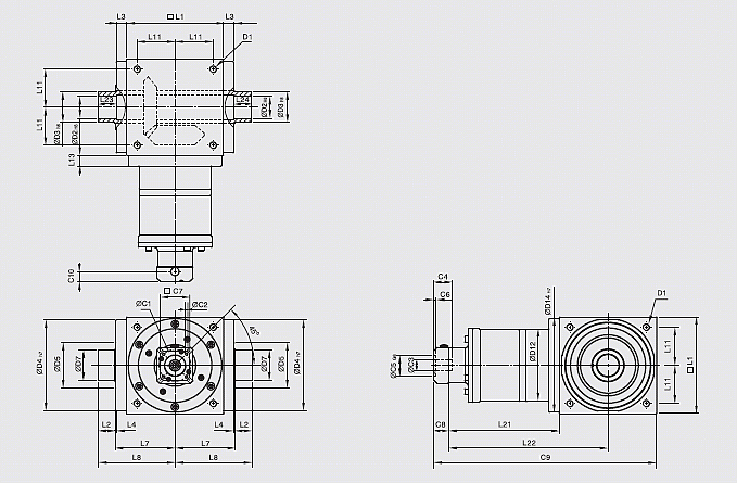
ATB-FC series 2-stage, ratio i = 7 ~ 50
| ATB065FC | ATB075FC | ATB090FC | ATB110FC | ATB140FC | ATB170FC | ATB210FC | ATB240FC | ATB280FC | |
| D1 | M4 | M6 | M6 | M8 | M10 | M12 | M16 | M16 | M16 |
| D2 H6 | 13 | 14 | 18 | 22 | 32 | 40 | 50 | 55 | 60 |
| D3 h8 | 16 | 16 | 22 | 25 | 44 | 50 | 62 | 68 | 75 |
| D4 h7 | 63 | 73 | 88 | 108 | 135 | 165 | 205 | 235 | 275 |
| D12 | 62 | 72 | 86 | 106 | 104 | 128 | 160 | 180 | 200 |
| D14 h7 | 63 | 73 | 88 | 108 | 135 | 165 | 205 | 235 | 275 |
| D15 | 62.9 | 72.9 | 87 | 107 | 106 | 127 | 158 | 178 | 198 |
| D17 | 26 | 26 | 36 | 38 | 61 | 70 | 86 | 86 | 100 |
| D18 | 41 | 41 | 50 | 50 | 80 | 90 | 110 | 115 | 138 |
| L1 | 65 | 75 | 90 | 110 | 140 | 170 | 210 | 240 | 280 |
| L2 | 14 | 14 | 18 | 18 | 24 | 26 | 29 | 29 | 30.5 |
| L3 | 13 | 14.5 | 15 | 15 | 15 | 15 | 20 | 25 | 25 |
| L4 | 2 | 2 | 2 | 2 | 2 | 2 | 2 | 2 | 2 |
| L7 | 47.5 | 54 | 62 | 72 | 87 | 102 | 127 | 147 | 167 |
| L8 | 66 | 72.5 | 85 | 95 | 116.5 | 133.5 | 161.5 | 181.5 | 205 |
| L11 | 27 | 30 | 36 | 44 | 55 | 67 | 85 | 95 | 110 |
| L13 | 13 | 15 | 15 | 15 | 15 | 15 | 20 | 25 | 25 |
| L21 | 75 | 84.5 | 99 | 122 | 144.5 | 157.5 | 206.5 | 239 | 248 |
| L22 | 107.5 | 122 | 144 | 177 | 214.5 | 242.5 | 311.5 | 359 | 388 |
| L23 | 15 | 15 | 20 | 20 | 26 | 28 | 31 | 31 | 32.5 |
| L24 | 15 | 15 | 20 | 20 | 26 | 28 | 31 | 31 | 32.5 |
| L25 | 15 | 15 | 19.5 | 19.5 | 25.5 | 27.5 | 30.5 | 30.5 | 32.5 |
| L26 | 18.5 | 18.5 | 23 | 23 | 29.5 | 31.5 | 34.5 | 34.5 | 38 |
| C1 3 | 46 | 46 | 70 | 100 | 100 | 100 | 130 | 165 | 165 |
| C2 3 | M4 | M4 | M5 | M6 | M6 | M6 | M8 | M10 | M10 |
| C3 3 | ≤12 | ≤12 | ≤16 | ≤24 | ≤24 | ≤24 | ≤32 | ≤38 | ≤38 |
| C4 3 | 30 | 30 | 34 | 40 | 40 | 40 | 50 | 60 | 60 |
| C5 3G6 | 30 | 30 | 50 | 80 | 80 | 80 | 110 | 130 | 130 |
| C6 3 | 3.5 | 3.5 | 8 | 4 | 4 | 4 | 5 | 6 | 6 |
| C7 3 | 42 | 42 | 60 | 92 | 92 | 92 | 115 | 142 | 142 |
| C8 3 | 21.5 | 21.5 | 21.5 | 20 | 20 | 20 | 24 | 31 | 31 |
| C9 3 | 161.5 | 181 | 210.5 | 252 | 304.5 | 347.5 | 440.5 | 510 | 559 |
| C10 3 | 14.5 | 14.5 | 15.5 | 13 | 13 | 13 | 16 | 21 | 21 |
3. C1~C10 are motor specific dimensions (metric std shown).
ATB-FC series 3-stage, ratio i = 75 ~ 500
| ATB110FC | ATB140FC | ATB170FC | ATB210FC | ATB240FC | ATB280FC | |
| D1 | M8 | M10 | M12 | M16 | M16 | M16 |
| D2 H6 | 22 | 32 | 40 | 50 | 55 | 60 |
| D3 h8 | 25 | 44 | 50 | 62 | 68 | 75 |
| D4 h7 | 108 | 135 | 165 | 205 | 235 | 275 |
| D12 | 106 | 104 | 128 | 160 | 180 | 200 |
| D14 h7 | 108 | 135 | 165 | 205 | 235 | 275 |
| D15 | 107 | 106 | 127 | 158 | 178 | 198 |
| D17 | 38 | 61 | 70 | 86 | 86 | 100 |
| D18 | 50 | 80 | 90 | 110 | 115 | 138 |
| L1 | 110 | 140 | 170 | 210 | 240 | 280 |
| L2 | 18 | 24 | 26 | 29 | 29 | 30.5 |
| L3 | 15 | 15 | 15 | 20 | 25 | 25 |
| L4 | 2 | 2 | 2 | 2 | 2 | 2 |
| L7 | 72 | 87 | 102 | 127 | 147 | 167 |
| L8 | 95 | 116.5 | 133.5 | 161.5 | 181.5 | 205 |
| L11 | 44 | 55 | 67 | 85 | 95 | 110 |
| L13 | 15 | 15 | 15 | 20 | 25 | 25 |
| L21 | 136.5 | 159.5 | 183.5 | 226 | 269 | 278 |
| L22 | 191.5 | 229.5 | 268.5 | 331 | 389 | 418 |
| L23 | 20 | 26 | 28 | 31 | 31 | 32.5 |
| L24 | 20 | 26 | 28 | 31 | 31 | 32.5 |
| L25 | 19.5 | 25.5 | 27.5 | 30.5 | 30.5 | 32.5 |
| L26 | 23 | 29.5 | 31.5 | 34.5 | 34.5 | 38 |
| C1 4 | 46 | 46 | 70 | 70 | 100 | 100 |
| C2 4 | M4 | M4 | M5 | M5 | M6 | M6 |
| C3 4 | ≤12 | ≤12 | ≤16 | ≤16 | ≤24 | ≤24 |
| C4 4 | 30 | 30 | 34 | 34 | 40 | 40 |
| C5 4G6 | 30 | 30 | 50 | 50 | 80 | 80 |
| C6 4 | 3.5 | 3.5 | 8 | 8 | 4 | 4 |
| C7 4 | 42 | 42 | 60 | 60 | 92 | 92 |
| C8 4 | 21.5 | 21.5 | 21.5 | 21.5 | 20 | 20 |
| C9 4 | 268 | 321 | 375 | 457.5 | 529 | 578 |
| C10 4 | 14.5 | 14.5 | 15.5 | 15.5 | 13 | 13 |
4. C1~C10 are motor specific dimensions (metric std shown).
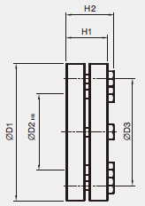
Shrink disc
| C / FC Serie | D1 | D2 | D3 | H1 | H2 |
| SSD-d16xdw14 | 41 | 16 | 26 | 15 | 18.5 |
| SSD-d22xdw18 | 50 | 22 | 36 | 19.5 | 23 |
| SSD-d25xdw22 | 50 | 25 | 38 | 19.5 | 23 |
| SSD-d44xdw32 | 80 | 44 | 61 | 25.5 | 29.5 |
| SSD-d50xdw40 | 90 | 50 | 70 | 27.5 | 31.5 |
| SSD-d62xdw50 | 110 | 62 | 86 | 30.5 | 34.5 |
| SSD-d68xdw55 | 115 | 68 | 86 | 30.5 | 34.5 |
| SSD-d75xdw60 | 138 | 75 | 100 | 32.5 | 38 |
Need help with your application? Our specialists are happy to use their years of experience to assist you in selecting the right products.
